28 февраля 2014 г.

Книга: настройка программной среды в Linux

Настройка программной среды в Linux

{это черновик}


В этом разделе будут подробно рассмотрены этапы установки и настройки различных программ и утилит, показаны примеры их использования.

В частности будут рассмотрены:

Avrdude - консольная программа для прошивки микроконтроллеров
AVR burn-o-mat - графическая оболочка к 
Avrdude
Avra - ассемблер 
 для AVR микроконтроллеров фирмы Atmel
Geane - удобная среда разработки. Рассмотрим 2 варианта атоматизации работ по компиляции кода / прошивки МК / правки Фьюзов.


23 февраля 2014 г.

Книга: avrdude

Avrdude: прошивка МК из консоли


Какие программные продукты потребуются? Потребуется 
avrdude - утилита для прошивки МК, которая поддерживает кучу разных программаторов и контроллеров.


Подготавливаем рабочее пространство
sudo apt-get install avrdude


Допустим имеется 
файл в прошивкой микроконтроллера Example.hex, который потребуется залить в контроллер. Допустим мы используем программатор USBasp.

Попробуем прошить программу в микроконтроллер:
avrdude -p t2313 -c usbasp -U flash:w:Example.hex

Опции:
-p - указывем тип контроллера, например для Tiny2313 именно t2313
-c - указываем используемый программатор, например usbasp
-U - указываем файл для прошивки и Модификаторы
flash:w: - модификаторы уточняют куда производить запись, во flash.

Однако нас огорчит ошибка:
avrdude: usb_open(): cannot read serial number "error sending control message: Operation not permitted"
Дело в том, что udev (линуксовый менеджер устройств), исходно не дает любому пользователю писать на какое попало устройство. Нам нужно подружить USBasp с udevом.

Найдем USBasp в списке подключенных устройств командой lsusb :
Bus 001 Device 001: ID 1d6b:0002 Linux Foundation 2.0 root hubBus 004 Device 001: ID 1d6b:0003 Linux Foundation 3.0 root hubBus 001 Device 002: ID 8087:0024 Intel Corp. Integrated Rate Matching HubBus 002 Device 003: ID 046d:c52f Logitech, Inc. Wireless Mouse M305Bus 003 Device 025: ID 16c0:05dc VOTI shared ID for use with libusb


Последняя строка - наша цель. 16с0 - это код производителя, а 05dc - это код устройства.
Нам нужно создать файл с правилом для udev, файл должен располагаться тут:
/etc/udev/rules.d/10-usbasp.rules

в нем должна быть строка описывающая само правило:
SUBSYSTEM=="usb", SYSFS{idVendor}=="16c0", SYSFS{idProduct}=="05dc", GROUP="adm", MODE="0666"

Правило означает, что мы дали пользователям, входящим в группу adm, права доступа 666 (запись и чтение) к устройству 16c0:05dc. На моем LinuxMint 15 пользователь под которым я работаю уже входил в группу adm (администраторы), поэтому в правиле указал именно её. Прописывание группы users и добавление себя в неё (как многие советуют) желаемого результата не давало, без sudo не запускалось.


Итого, нам требуется дать в консоле такую команду:
echo 'SUBSYSTEM=="usb", SYSFS{idVendor}=="16c0", SYSFS{idProduct}=="05dc", GROUP="adm", MODE="0666"' | sudo tee /etc/udev/rules.d/10-usbasp.rules

Перезапустим сервис udev, чтобы правило вступило в силу:
sudo restart udev

Отсоединяем USBasp от порта, выходим из учетки, потом заходим снова и подсоединяем USBasp. Avrdude должен начать запускаться без sudo. [смутно помню потребовалось ли выходить из учетки, или после рестарта udev все уже заработало...]


*************************************************************************


Прошивка консольной утилитой avrdude

Для того,чтобы залить прошивку в микроконтроллер необходимо выполнить команду:
avrdude -c usbasp -p m8 -U flash:w:имя_файла.hex
где -p m8 - это модель микроконтроллера.В данном случае atmega 8.


Дополнительно можно прошить и фьюзы, дописав:
-U hfuse:w:0xХХ:m -U lfuse:w:0xХХ:m
Где ХХ - соотвествующие фьюзы микроконтроллера, необходимые для конкретной прошивки.

На некоторых микроконтроллерах (например на серии ATtiny) включен по умолчанию фьюз CKDIV8, который устанавливает делитель на 8 и из-за этого USBasp не программирует такие микроконтроллеры пока не установить перемычку JP3 на плате USBasp.


*********************************************************************


Для настройки фьюзов

Для настройки фьюзов воспользуйтесь калькулятором фьюзов чтобы выставить нужные настройки, в том числе выключить делитель CKDIV8.
Фьюзы прошиваются через командой
avrdude -c usbasp -p имя_м/к -U lfuse:w:0xХХ:m

Например для установки фьюзов attiny85 для внутреннего генератора 8мгц с выключенным делителем на 8 пордам команду:
avrdude -c attiny85 usbasp -p -U lfuse:w:0x62:m

При программировании через Arduino IDE можно установить нужные фьюзы выбрав в меню "записать загрузчик", выбрав перед этим необходимый микроконтроллер.

***********************************************************


Пробуем работать с avrdude
Подключаем любой МК, попробуем считать его сигнатуру:

avrdude -c usbasp -p t13 -F
avrdude: warning: cannot set sck period. please check for usbasp firmware update.avrdude: AVR device initialized and ready to accept instructionsReading | ################################################## | 100% 0.00savrdude: Device signature = 0x1e9007avrdude: safemode: Fuses OKavrdude done. Thank you.


Видим что все как-бы в порядке... , программа выдала варнинг, но успешно считала сигнатуру. Кстати, 0x1e9007 это TINY13.


****************************************************************


Книга: Автоматизация Geany на основе MAKE файлов

Автоматизация Geany.
Вариант 2: на основе MAKE файлов.


Это достаточно удобный способ может сперва показаться слишком запутанным... В папке с каждым проектом создается Makefile в котором указывается указываем модель контроллера, фьюзы, путь к компилятору и его конкретный вариант avra/gavrasm/gcc-avr, модель программатора и программа прошивки.

Если в процессе разработки мы понимаем, что далее требуется начать работать с другой конфигурацией и контроллером, редактируем три строчки в начале make-файла.

Итак, создадим новый проект в Geany. В настройках выбирем: Сборка- Установить команды сборки. Появится такое меню:


Настоим - для этого нужно прописать следующие команды (названия произвольные):
"Скомпилировать" -  make compile FILE=%e
"Прошить" - make program FILE=%e
"Очистить" - make clean FILE=%e
"Взвесить" - make size FILE=%e


Теперь нужно написать собственно сам make-file и положить его в папку проекта.
Это удобная система, потом при любом проекте указываем модель контроллера, фьюзы и готово. По моему даже лучше чем выбирать из списка всё это в окнах настройки проекта. Естественно, makefile можно создать и получше но тут будет совсем простой для простых проектов.
Не забываем про табуляцию перед командой, иначе будет ошибка.


Файл выглядит так:

# Makefile for programming AVR in Geany
#Параметры проекта:

MK=t13
LFuse=0x7A
HFuse=0xFF

# Более глобальные переменные. 
ASM=avra
ISP=avrdude
INCLUDEDIR=/usr/share/avra/includ

compile:
    $(ASM) -I $(INCLUDEDIR) -l $(FILE) $(FILE).asm 2>&1|grep -v PRAGMA
program : $(FILE).hex
    $(ISP) -c usbasp -p $(MK)  -U flash:w:$(FILE).hex:i -U lfuse:w:$(LFuse):m -U hfuse:w:$(HFuse):m
clean:
    rm -f $(FILE).cof $(FILE).eep.hex $(FILE).hex $(FILE).obj *~
size:
    avr-size  $(FILE).hex
Теперь правим его под себя - указываем тип своего МК и fuse.
Не забываем про табуляцию перед командой, иначе будет ошибка. Также, некоторые редакторы вставляют в файл свои невидимые символы BOM в результате чего тоже будет ошибка. Советую править Makefile используя geany, с ним проблем невидимых символов и табуляции не будет.

Обычно выдается ошибка такого вида:

Makefile:1: *** пропущен разделитель. Останов.
Впрочем, можно не мучатся и просто скачать данный образец:
wget https://sites.google.com/site/httpavrprogblogspotru/Makefile


ИТОГО, в Geany доступны автоматические действия:
"Компилировать" - или иконка с пирамидой и шаром, или F8
"Взвесить" -
"Прошить" - иконка с шестеренкой, или F9

Все "наши" созданные команды содержатся в пункте верхнего меню Сборка.

22 февраля 2014 г.

Книга: Geany автоматизация 1

Автоматизация Geany.
Вариант 1: простой и универсальный.


Теперь запускаем Geany, создаем новый файл или открываем любой исходник .asm, открываем вкладку "Сборка" / "Установить команды сборки".
Видим окно настройки пользовательских команд:


В соответствующие поля вводим команды команды: 

"Скомпилировать" - avra --includepath /usr/share/avra/includes %f
"Фьюзы" - avr8-burn-o-mat
"Размер" - avr-size  %e.hex
"Очистить" - rm -f %e.cof $e.eep.hex %e.hex %e.obj
"Прошить" - PART=`grep -m 1 -e "^\.include " %f | sed -r -e 's/.*include "(.+)def\.inc".*/\1/' | sed "s/tn/t/g"` && echo "target device: $PART" && avrdude -p $PART -c usbasp -U flash:w:"%e.hex" && exit

Пояснения:
%f - шаблон geany, имя текущего файла (в нашем случае это Example.asm)
%e
шаблон geany, имя текущего файла без расширения (Example)
%dшаблон geany, путь к папке, в которой лежит текущий файл (~/Projects/AVR/Example/)
%pшаблон geany, путь к текущему проекту (~/Projects/AVR/Example/)
PART - строковая переменная, в которую заносится результат выполнения скрипта, определяющего тип контроллера
echo "target device: $PART" - выводим в консоль название распознанного контроллера (исключительно как информация вам для справки)
avrdude -p $PART -c usbasp -U flash:w:"%e.hex" - запускаем avrdude, подставляя в него нужную опцию
grep -m 1 -e "^\.include " %f - находит строчку начинающуюся на .include, опция -m 1 указывает что не стоит продолжать поиск, если хотя бы 1 строка уже найдена.
sed -r -e 's/.*include "(.+)def\.inc".*/\1/' - из найденной строки с помощью шаблона вычленяется название контроллера (все что после кавычки и перед def.inc).
sed "s/tn/t/g" - заменяет tn на t. так как в аппноутах Tiny2313, например, зовется tn2313, а avrdude ее понимает как t2313. 

Чтобы Geany сам распознавал тип микроконтроллера и менял опцию -p в команде avrdude нужно в исходном файле анализировать строки вида .include "m8def.inc", которые указывают тип используемого микроконтроллера и присутствуют в каждом asm файле.

Полезная и приятная особенность данного скрипта: так как для связки команд используется операнд &&, то следующая команда выполняется только в случае успешного завершения предыдущей. Таким образом, если строка .include не была найдена в файле, или при прошивке что-то пошло не так - терминал останется открытым и мы сможем прочитать сообщения о случившихся ошибках.


Для прошивки Фьюзов используется графическая оболочка к avrdude AVR8_Burn-O-Mat.


Теперь для того чтобы:
Скомпилировать код - нужно нажать F8 (или иконку с пирамидой и шаром), 
Прошить код в микроконтроллер - нажать F5 (или иконку с шестеренкой),
Править Фьюзы - нажать F9 (или иконка с кирпичем).


____Приведенная в этой заметке команда "Прошить" - PART=`grep -m 1 -e "^\.include " %f | sed -r -e 's/.*include "(.+)def\.inc".*/\1/' | sed "s/tn/t/g"` && echo "target device: $PART" && avrdude -p $PART -c usbasp -U flash:w:"%e.hex" && exit отличается от наличествующих в интернете подобных описаний Geany. Отличается в лучшую сторону: во-первых она действительно работает (LinuxMint15), во-вторых корректно распознает все имена поддерживаемых контроллеров.


Книга: AVR8 Burn-O-Mat

Утилита AVR8 Burn-O-Mat


Да, avrdude позволяет прошивать и фьюзы, но для этого нужно по даташиту на ваш микроконтроллер заранее вручную посчитать fuse, перевести их в шестнадцатеричную систему и указать avrdude в командной строке.

Такая команда могла бы выглядеть подобным образом:
avrdude -p е2313 -c usbasp -U hfuse:w:0xХХ:m -U lfuse:w:0xYY:m
где XX и YY заранее вычисленные hfuse и lfuse.

Учитывая высокую вероятность ошибки и крайнюю трагичность последствий этой ошибки, такой вариант прошивки фьюзов не всегда оптимален. Существует графическая оболочка к avrdude - AVR8 Burn-O-Mat.


Вот сайт этой программы: http://avr8-burn-o-mat.aaabbb.de/avr8_burn_o_mat_avrdude_gui_en.html

Качаем deb-пакет с сайта, пробуем установить...
У меня пакет устанавливаться не захотел, выдавал ошибку:
dpkg: ошибка при обработке параметра avr8-burn-o-mat-2.1.2-all.deb (--install):
анализ файла «/var/lib/dpkg/tmp.ci/control» около строки 2 пакета «avr8-burn-o-mat»:
ошибка в строке Version «REPLACE_PROG_VERSION»: номер версии не начинается с цифры
Желающие могут скачать Sourcecode AVR8 Burn-O-Mat, и откомпилировать, остальным же предлагаю воспользоваться уже "починенным" пакетом, действуем так:
wget http://radiokot.ru/articles/52/02.zip
unzip 02.zip
dpkg -i avr8-burn-o-mat-2.1.2.deb

При первом запуске AVR8_Burn-O-Mat потребуется его настроить. Для этого перейдем во вкладку Settings - AVRDUDE:


Теперь нужно ввести путь к avrdude, путь к файлу с его настройками, тип вашего программатора и порт к которому он подключен. Настраиваем так, как показано на скрине.

Всё, теперь можно выбрать нужный вам контроллер, нажать Fuses и править их как надо.

Перед исправлением Fuses, обязательно сначала считывайте их с кристалла! Да и вообще, поаккуратней с ними ;)

Книга: установка Geany

Среда Разработки Geany

Итак, мы научились компилировать исходный код на ассемблере используя командную строку и компилятор avra. Настало время освоить какую-либо Среду Программирования, чтобы можно было сосредоточить все свои способности именно на программировании. Начнем с самой простой - Geany.

В отличие от текстовых редакторов Geany является именно Средой Разработки, поэтому в ней есть так нужные нам абстрактные действия: компиляция, сборка, запуск. Причем можно задать какие именно команды должны выполняться в этих действиях. Таким образом, мы получаем возможность назначить запуск avra (или gcc-avr если будем писать на Си) на действие "компиляция", назначить вызов avrdude на "запуск". Действие же "сборка" будем использовать для установки фьюзов.


Установка Geany

sudo apt-get install geany


Настройка стиля подсветки синтаксиса Ассемблера
Сделаем хороший стиль подсветки синтаксиса ассемблера. Для этого откроем файл:

gedit ~/.config/geany/filedefs/filetypes.asm
и вставим в редакторе текст вот с этой страницы: http://wiki.geany.org/config/avr_asm
или этот текст можно скачать себе так:

wget http://wiki.geany.org/_export/code/config/avr_asm
Редактируем и сохраняем модифицированный filetypes.asm.


Далее, мы рассмотрим варианты автоматизации 
Geany:  запуск процесса компиляции, прошивка микроконтроллера, и установка фьюзов. Существуют минимум два варианта автоматизации.


содержание книги

Книга: ассемблер AVRA

Ассемблер AVRA

AVRA является ассемблером для AVR микроконтроллеров фирмы Atmel, и он почти полностью согласован с собственным Atmel ассемблером AVRASM32. Если вы решились писать на ассемблере в linux не используя wine и AVRStudio, вам придется работать в AVRA.


Различия между AVRA и атмеловским AVRASM32
Существуют некоторые различия между оригинальным Atmel-овским ассемблером AVRASM32 и AVRA.
  • Поддержка некоторых дополнительных директив препроцессора (.define, .undef, .ifdef, .ifndef, .if, .else, .endif, .elif, .elseif, .warning)
  • Не все параметры командной строки поддерживаются. Указание от дельного файла для eeprom(-e) не поддерживается. Все данные для eeprom помещаются в файл называемый program.eep.hex и всегда в Intel hex формате. Другие форматы hex файлов, помимо Intel на данный момент не поддерживаются.
  • Опережающие ссылки(ссылка на класс, переменную или функцию, которые объявлены, но еще не определены) не поддерживаются для .ifdef и .ifndef директив. Это гарантирует , что директивы такие как .ifdef и .undef будут работать правильно. Если вы знакомы с языком программирования C , вы легко это получите в AVRA. 
  • Расширенная поддержка макросов в AVRA имеет некоторые новые функции для написания гибких макросов. Это должно увеличить возможность повторного использования кода например построить вашу собственную библиотеку.
  • Поддержка отладки, AVRA создает coff файл каждый раз когда сборка завершается успешно. Это файл так же как и в AVR Studio или любой другой coff совместимом отладчике используется для имитации или эмуляции программы.
  • Мета теги времени сборки. Это поможет вам отслеживать версии вашего программного обеспечения, а также может быть использовано для создания заказных серийных номеров.

Особенности спользования директив
AVRA предлагает целый ряд директив, которые не являются частью Atmel ассемблера. Эти директивы должны помочь вам создать универсальный код, который может быть разработан более модульным.

Директива .define
Чтобы задать константу, используйте .define . Это то же самое что и .equ, только более C стиле. Имейте ввиду что AVRA не чувствительна к регистру. Не смешивайте .def и .def ine, потому что .def используется только для регистров. Это сделано для обратной совместимост и с Atmel-овским AVRASM32.
Вот пример того как использовать .define:
.define network 1
Теперь «network» установлена значение 1. Вы можете собрать определенные части вашего кода в зависимости от определителей или переключателей. Вы можете проверить ваши определенные переменные на существование (.ifdef и .ifndef ), а также на значение которое они подcтавляю. В следующем коде показан способ предотвратить сообщение об ошибке при тестировании неопределенной константы. Условные директивы всегда должны заканчиваться директивой .endif
.ifndef network
.define net work 0
.endif


Директивы .if и .else
Три строчки последнего примера устанвливают значения по умолчанию для «network». В следующем примере, вы увидете как мы можем использовать значения по умолчанию. Если не была определена ранее, она устанавливается в ноль. Теперь вы можете проверить , входит ли поддержка сети в процесс сборки.
.if network = 1
.include "include\tcpip.asm"
.else
.include "include\dummynet.asm"
.endif

Во второй части листинга выше вы видите использование .else, которая определяет часть которая будет выполнена если выражение в предыдущем .if не равно. Вы также можете использовать другое выражение для проверки другого выражения. Для этой цели используется .elif , что означает «else if». Всегда закрывайте эту условную часть «.endif »


Директива .error
Эта директива может быть использована чтобы выдавать ошибки, если часть кода достигла того, чего не должна была достигнута. В следующем примере показано как остановить процесс сборки ,если имеет значение то что значение не было установлено.
.ifndef network
.error "network is not configured!" ;the assembler stops here


Директивы .nolist и .list
Вывод списка файлов может быть остановлено этими двумя директивами. После того как только avra обнаруживает при сборке .nolist , это останавливает вывод списка файлов. После того как директива .list обнаружена, она продолжает нормальный вывод файлов.


Директива .includepath
По умолчанию, любой файл, который включается изнутри файла с исходным кодом, должен иметь либо только имя файла полный абсолютный путь к файлу. С директивой .includepath вы можете установить дополнительные пути поиска файлов. Кроме того вы можете добавить множество нужных вам путей. Убедитесь что нет схожих имен файлов в разных включениях, потому что , тогда не ясно какой из них avra использовать.


Установка AVRA в Linux
Нам понадобиться именно последняя версия avra - 1.3.0, а не содержащаяся в стандартном репозитории версия 1.2.3. Почему? Потому, что она спокойно воспринимает записи #ifndef ,#define ,#pragma в заголовочных файлах (эти директивы появились в AVRASMv2), вы конечно можете исправить их на .ifndef , .define, а #pragma игнорировать, но в версии 1.3.0 это уже учтено.
Качаем архив
wget http://downloads.sourceforge.net/project/avra/1.3.0/avra-1.3.0.tar.bz2


распаковываем
tar -xf avra-1.3.0.tar.bz2


переходим в папку с src-файлами
cd avra-1.3.0/src
Для сборки программе очень нужно, чтобы в папке src лежали файлы NEWS, README, AUTHORS и ChangeLog, которых там нет.
README, AUTHORS лежат в соседней папке, перенесем их:
cp ../AUTHORS ../README ../src
Двух других файлов нигде нет, создадим их пустыми :
touch ChangeLog NEWS
Теперь по порядочку выполняем команды:
aclocal
autoconf
automake -a
./configure
sudo make
sudo make install

Все готово. Проверяем:
avra --version
Получаем:
AVRA: advanced AVR macro assembler Version 1.3.0 .......


Теперь скопируем папку includes (содержащую *.def файлов) в /usr/share/avra:
cd ..
sudo mv includes/ /usr/share/avra

Для проверки работы напишем простейшую тестовую программу.
.includepath "/usr/share/avra/includes/" ; Папка с файлами заголовками
.include "m16def.inc" ; Используем ATMega16
; RAM
;=====================================================
.DSEG
; Сегмент ОЗУ
; FLASH
;===================================================
.CSEG
; Кодовый сегмент
; EEPROM
;==================================================
.ESEG
; Сегмент EEPROM
; FLASH
;===================================================
main:
ldi r19 , 0xFF ;
out DDRB, r19
REB:
ldi r17, 0xFF
Program:
out PORTB, r17
rjmp Program

Программа даже не мигает светодиодом, а просто светит всем портом B.
Сохраните файл с расширением .s, например first.s, и перейдя в папку с программой введите:
avra first.s

У вас может выскочить ошибка такого рода:
/usr/share/avra/includes/m16def.inc(534) : Error : Line to long
Это значит, придется открыть /usr/share/avra/includes/m16def.inс и укоротить длиннющий комментарий в 534 строке. После того все должно работать.

В итоге должно вывестись что нибудь вроде этого:
done
Used memory blocks:
Assembly complete with no errors.
Segment usage:
   Code      :        5 words (10 bytes)
   Data       :        0 bytes
   EEPROM:      0 bytes


21 февраля 2014 г.

уровень 2: ассемблер AVRA, среда программирования Geany


AVRA является ассемблером для AVR микроконтроллеров фирмы Atmel, и он почти полностью согласован с собственным Atmel ассемблером AVRASM32. Если вы решились писать на ассемблере в linux не используя wine и AVRStudio, вам придется работать в AVRA.

AVR8 Burn-O-Mat: a GUI for avrdude

AVR8 Burn-O-Mat: a GUI for avrdude

В качестве GUI оболочки для avrdude используем AVR8 Burn-o-mat v2. В связи с тем, что последнее обновление было еще в далеком 2009 году, установка требует небольших извращений.

9 февраля 2014 г.

Первый уровень

это наброски
_________________________________________________


Первое подключение программатора к компу, настройка прав доступа

Итак, первое подключение программатора к компу. Программатор никак еще не модернизирован, все в заводском виде. Подключаем и проверяем, как видится он на шине USB ...

$ lsusb
Bus 002 Device 006: ID 16c0:05dc VOTI shared ID for use with libusb

Кажется все в порядке, среди прочих строк видим и наш ID 16c0:05dc. 16с0 - это код производителя, а 05dc - это код устройства. USBasp так и должен определяться системой.


Теперь пробуем запустить утилиту для работы с программатором - avrdude (не подключая никакого микроконтроллера, и даже не имея файла с прошивкой)

$ avrdude -p t2313 -c usbasp -U flash:w:Example.hex
avrdude: Warning: cannot query manufacturer for device: error sending control message: Operation not permitted
avrdude: error: could not find USB device "USBasp" with vid=0x16c0 pid=0x5dc

Выдается ошибка на отсутствие прав доступа. Исправим это. Нужно создать файл с правилом для udev, файл должен располагаться тут:
       /etc/udev/rules.d/10-usbasp.rules

в нем должна быть строка описывающая само правило:
SUBSYSTEM=="usb", SYSFS{idVendor}=="16c0", SYSFS{idProduct}=="05dc", GROUP="adm", MODE="0666"

Она означает, что мы дали пользователям, входящим в группу adm, права доступа 666 (запись и чтение) к устройству 16c0:05dc. На моем LinuxMint 15 пользователь под которым я работаю уже входил в группу adm (администраторы), поэтому в правиле указал именно её. Прописывание группы users и добавление себя в неё (как многие советуют) желаемого результата не давало, без sudo не запускалось :(

Итого, нам требуется дать в консоле такую команду:
$ echo 'SUBSYSTEM=="usb", SYSFS{idVendor}=="16c0", SYSFS{idProduct}=="05dc", GROUP="adm", MODE="0666"' | sudo tee /etc/udev/rules.d/10-usbasp.rules

Перезапустим сервис udev, чтобы правило вступило в силу:
$ sudo restart udev


Отсоединяем USBasp от порта, выходим из учетки, потом заходим снова и подсоединяем USBasp. Avrdude должен начать запускаться без sudo. [смутно помню потребовалось ли выходить из учетки, или после рестарта udev все уже заработало...]


Пробуем работать с avrdude
Подключаем любой МК, попробуем считать его сигнатуру:

$ avrdude -c usbasp -p t13 -F

avrdude: warning: cannot set sck period. please check for usbasp firmware update.
avrdude: AVR device initialized and ready to accept instructions
Reading | ################################################## | 100% 0.00s
avrdude: Device signature = 0x1e9007
avrdude: safemode: Fuses OK
avrdude done.  Thank you.

Видим что все как-бы в порядке... , программа выдала варнинг, но успешно считала сигнатуру. Кстати, 0x1e9007 это TINY13. 


Попытаемся прошить какой-нибудь микроконтроллер
Программатор упорно не хочет шить, ругается на ошибку верификации после записи, и
опять выводит варнинг...

$ avrdude -c usbasp -p t13   -Uflash:w:blink_led.hex:a

avrdude: warning: cannot set sck period. please check for usbasp firmware update.
avrdude: AVR device initialized and ready to accept instructions
Reading | ################################################## | 100% 0.00s
avrdude: Device signature = 0x1e9007
avrdude: NOTE: FLASH memory has been specified, an erase cycle will be performed
         To disable this feature, specify the -D option.
avrdude: current erase-rewrite cycle count is 167772159 (if being tracked)
avrdude: erasing chip
avrdude: warning: cannot set sck period. please check for usbasp firmware update.
avrdude: reading input file "blink_led.hex"
avrdude: input file blink_led.hex auto detected as Intel Hex
avrdude: writing flash (628 bytes):
Writing | ################################################## | 100% 0.34s
avrdude: 628 bytes of flash written
avrdude: verifying flash memory against hex.hex:
avrdude: load data flash data from input file hex.hex:
avrdude: input file blink_led.hex auto detected as Intel Hex
avrdude: input file blink_led.hex contains 628 bytes
avrdude: reading on-chip flash data:
Reading | ################################################## | 100% 0.18s
avrdude: verifying ...
avrdude: verification error, first mismatch at byte 0x0000
         0x09 != 0xff
avrdude: verification error; content mismatch
avrdude: safemode: Verify error - unable to read lfuse properly. Programmer may not be reliable.
avrdude: safemode: Sorry, reading back fuses was unreliable. I have given up and exited programming mode
avrdude done.  Thank you.


В данном месте стоило бы попытаться замкнуть 25-ю ножку МК программатора на землю (отсутствующая перемычка JP3), это бы включило пониженную частоту тактирования SCK, и наверняка подопытная TINY13 прошилась бы... но я избрал другой путь - перепрошить сам программатор стандартной прошивкой.

Решение принято - перепрошить сам программатор. Каким образом? Будем использовать имеющийся Arduino UNO.


Arduino UNO в качестве программатора
Запускаю среду разработки ARDUINO IDE
$ sudo ./arduino    (без sudo не давался доступ для смены порта)

выбираю плату (arduino UNO)
выбираю порт (/dev/ttyACM0)
заливаю в ардуину стандартный скетч ArduinoISP

Как рекомендуют подключаю конденсатор емкостью 10 мкф между RESET и GND на ардуине. 

Чтобы перестраховаться и не угробить USBasp программатор, пробую прошить TINY13.
Устанавливаю TINY13 на макетку. Подключаю от 10...13 выводов ардуины  к ней сигналы. Схема включения такова:
10: RESET
11: MOSI
12: MISO
13: SCK

Нахожу готовую прошивку для TINY13, мигающую светодиодом - blink_led.hex. Прошиваю:
$ sudo avrdude -p t13 -P /dev/ttyACM0 -c avrisp -b 19200 -U flash:w:blink_led.hex

Оп... и замигал светодиодик. Кажется что-то начинает получаться...


Теперь прошиваю МК в USBasp через Arduino UNO

для теста дал такую команду
$ sudo avrdude  -c avrisp -P /dev/ttyACM0 -b 19200 -p m8 -v
Шьем последнюю доступную прошивку взятую c сайта usbasp
$ sudo avrdude -c avrisp -P /dev/ttyACM0 -b 19200 -p m8 -U flash:w:usbasp.atmega8.2011-05-28.hex -v


Прошивается все успешно, но все дальнейшие попытки общаться нового USBasp с различными МК приводят к перманентным фатальным ошибкам:

$ avrdude -c usbasp -p atmega8 

avrdude: error: programm enable: target doesn't answer. 1 
avrdude: initialization failed, rc=-1
         Double check connections and try again, or use -F to override
         this check.

Находясь в грустных мыслях о загубленном программаторе, все же пробую замкнуть 25-ю ножку МК USBasp на землю, впаиваю перемычку. Частота SCK понизилась, и в таком режиме все подключаемые МК начали видеться и программироваться нормально.


Финальная модификация программатора
1) впаял джампер JP2 - чтобы в будущем при перепрограммировании не мучаться с проволочками...
2) впаял джампер JP3 - установил его около USB разъема, приклеим к плате суперклеем, в пластиковом корпусе сделал отверстие под джампер

::::::::::::::::::::::::
:::::::фото:::::::::
::::::::::::::::::::::::


ВЫВОДЫ
- JP3 нужно было сразу установить, а не мучить программатор перепрошивкой; подключаемые микроконтроллеры наверняка увиделись бы и с исходной китайской прошивкой USBasp.
- на низкой частоте SCK скорость прошивки МК кажется слишком медленной, впрочем так оно и есть. Без перемычки JP3 скорость программирования ~5 КБайт/с, с перемычкой на Slow SCK ~0,1 КБайт/с.
- радует, что со стандартной прошивкой перестали выводиться варнинги "cannot set sck period. please check for usbasp firmware update."


Нулевой уровень


Вводная статья. Она описывает используемый мною программатор, его положительные и отрицательные стороны, показывает общие принципы подключения программатора к микроконтроллеру.

5 февраля 2014 г.

ATTiny13 Заметки

Порты

Регистр DDRB=0 - переключение порта на вход,
DDRB=1 - переключение порта на выход
При DDRB=0, PORTB=1 включает подтягивающий регистр

4 февраля 2014 г.

перешиваем USBasp в USB-doper

На сегодняшний день имеются схемные и программные решения последовательных программаторов, которые могут сообщаться с ПК посредством USB портов. Здесь я приведу реализацию двух USB-программаторов: USBASP и USB-DOPER. Более подробно отличия и сходства я приведу позже. Пока только могу сказать, что схемные решения абсолютно не отличаются, а отличия лишь в программном коде.
USB-doper
  А вот эта интересная вещь способна стыковаться с AVRstudio. Программа видит этот программатор как STK-500. Очень удобно, когда программу откомпилировал, отладил и сразу же нажал на кнопочку – прошил.

   Чем же USBdoper отличается от USBasp? Физически ничем!! Принципиальная схема их абсолютно одинакова!!!! Поэтому, если у вас уже есть USBasp , то чтобы превратить этот программатор на псевдо STK-500 , достаточно поменять прошивку программатора вот на этот HEX. Единственное, замечу что применять исключительно Mega8.

  Теперь что нужно делать, чтобы все заработало:

    - возьмем наш готовый USB-asp и перешьем его мегу8 прошивкой, которая находится в скачаной папке (фаил avr-doper-mega8-12mhz.hex ).  Конечно же для прошивки нужен другой программатор.
    -устройство USB -doper готово. После чего компьютер обнаружит сразу же новое USB-устройство, скармливаем м драйвером и пользуемся. Драйверы приведены в той же скаченом папке, для Windows XP свой ,для Windows Vista свой драйвер.
   - после того, как все будет верно сделано устройство будет определятся в деспетчере устройств, как communications port. При подключении Winows должен определить устройство USB-doper.
   -далее после всего этого открываем AVRstudio, ваше устройство там обнаруживается как STK -500. Находим в AVRStudio, Tools -> Programm AVR -> Connect... и шьем).
  По скольку наш программатор не является фирменой продукцией фирмы ATMEL,  нам будет почти сразу же предложено обновить через интернет программное обеспечение. Отклоняйте подобные предложения.
  Кстати, у меня этот программатор работает только без перемычки J3 и J1 !
 
ПО для USB -doper качаем здесь

  Не будем нарушать авторские права.:-) Все это чудо придумано не мною, открыто товарищем
   
 
Для любителей шить МК в Си-коде USB-Doper также совместим и CodeVision.


  Еще одно! Бывает такое, что програматор не хочет съедать  драйвер на вашем компе. Приходится помучаться и тогда на раз ...надцатый выйдет. Это происходит из-за того что плохое согласование уравней программатор-компьютер. С этим борятся обычно подпаивая к выводам D+ и D- стабилитроны на 3,6 В.   


____
http://microelectronic.at.ua/publ/programmator_s_usb/1-1-0-6

3 февраля 2014 г.

Светодиодная гирлянда на tiny13

Схема светодиодной гирлянды 
Принципиальная схема гирлянды
Запаиваем детали и получаем следующее устройство:
Готовая плата


Для установки фьюз битов в меню "Command" выберите "Security and Configuration Bits…", в появившимся окне нажмите кнопку "Read" и установите галочки как на картинке ниже:
Установка фьюзов


Устройство имеет 4 разных эффекта:
1. Бегущая точка
2. Бегущая линия
3. Переключение светодиодов
4. Моргание

Скачать прошивку, исходники, проект в Proteus: Attiny13Led.rar (34 Кб)


___
http://cxem.net/mc/mc96.php

12 LED KITT-scanner


12 LED KITT scanner
Prototype of the KITT-scanner on a small piece of veroboard

12 LED KITT-scanner
The famous visual effect from the TV-series Battlestar Galactica and Knight Rider


A 12 LED KITT scanner with trail.

Often this kind of gadgets have no trail effect, but just a single LED moving visually back and forth. In the TV-series Knight Rider or Battlestar Galactica you saw clearly a trail effect in the visual motion, the same way you see in the gif animation on this webpage. Here one with a trail effect, using an ATtiny15L or ATtiny13 AVR microcontroller, the applied technique called charlieplexing.
Download hex file for ATtiny13  *.hex file.


Diagram of a 12 LED KITT scanner (charlieplexed)


____
http://members.ziggo.nl/electro1/avr/kitt.htm

Лампа настроения на ATTiny13


Лампа настроения - это светодиодный RGB светильник, плавно меняющий цвет свечения случайным образом. Мне хотелось сделать лампу на основе самого примитивного AVR микроконтроллера ATTINY13.
Схема получившейся лампы тривиальна:Схема лампы настроения
Мощный RGB-светодиод подключен к микроконтроллеру через полевые транзисторы. Для изменения яркости свечения использован самопальный трехканальный ШИМ. Светодиод я использовал трехватный RGB. В качестве блока питания - дешевое зарядное устройство для сотового телефона, с напряжением около 5.5В. Микроконтроллер и транзисторы использованы в SMD корпусах.
Алгоритм работы следующий:
  • случайным образом генерируется значение RGB цветовой точки и интервал времени, через которое этот цвет будет достигнут
  • чтобы цвета получались "красивыми" один из RGB компонент случайным образом зануляется
  • на прерывании таймера-счетчика висит обработчик самодельного ШИМа, а через каждый цикл итерации ШИМа вычисляется текущие цвета свечения светодиодов

Для записи прошивки использовал avrdude:

avrdude -c usbasp -pt13 -u -Ulfuse:w:0x7A:m -Uhfuse:w:0xFF:m -Uflash:w:moodlamp.hex:a


The Compleat ATtiny13 LED Flasher


This is the first part of three in attempting to explain how to make the ATtiny13 flash a LED.
If you’re used to the user-friendliness of Arduino, getting started with bare bones AVRs can be hard work.  I’d like to try to go slowly through the early steps and point out some of the information sources I used.
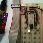
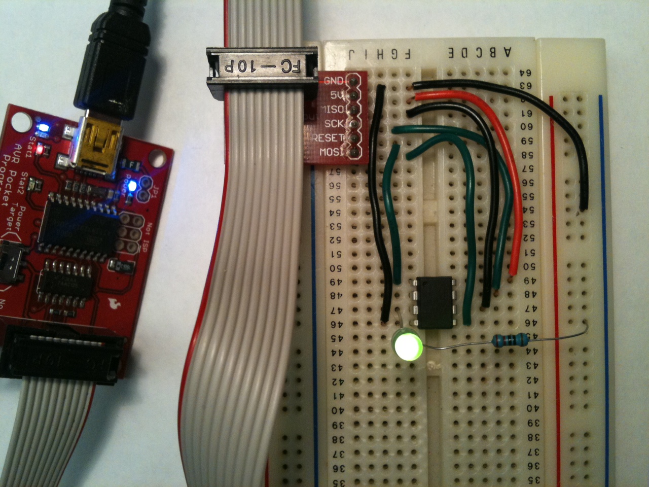
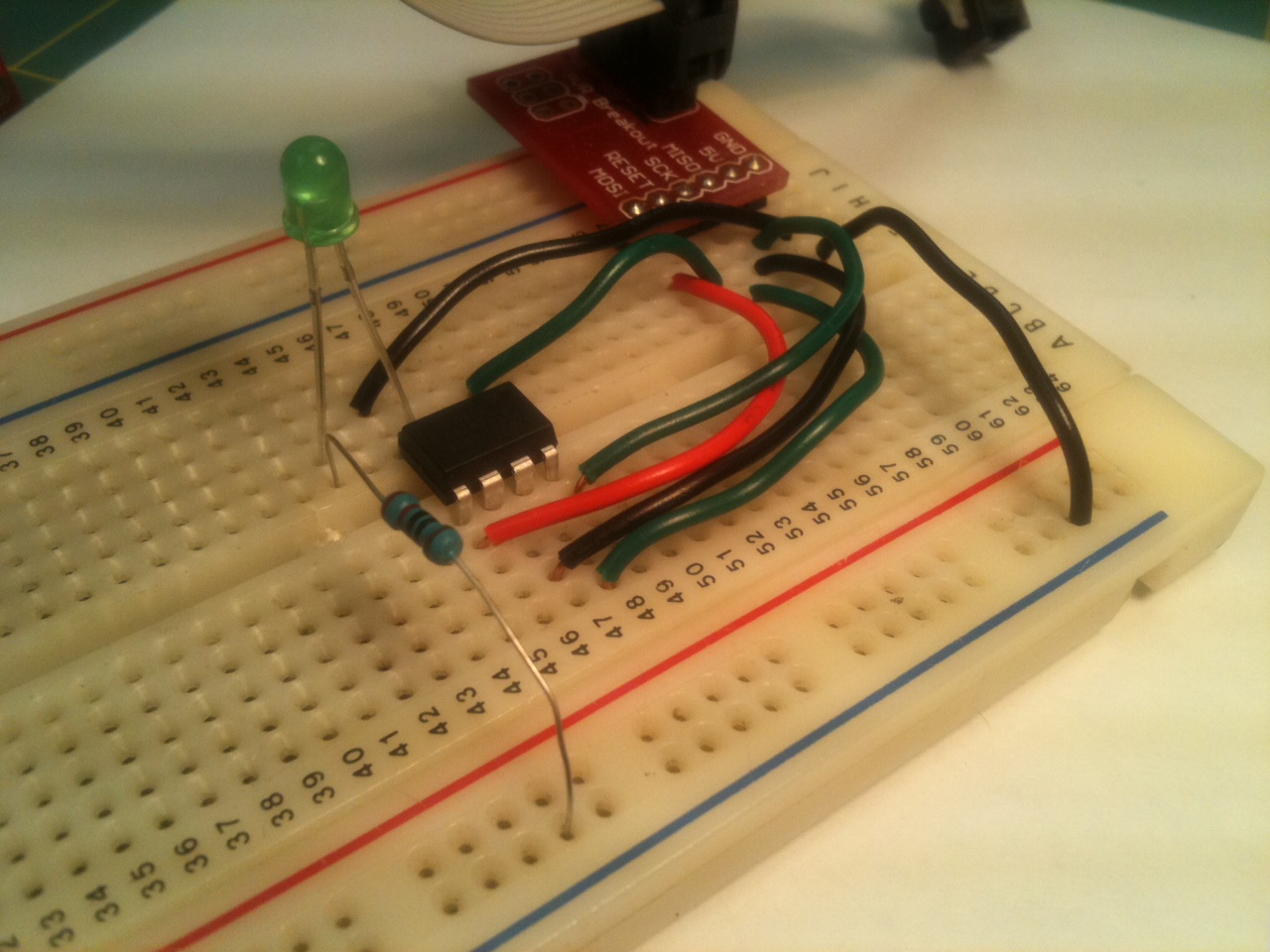
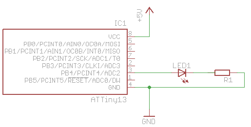
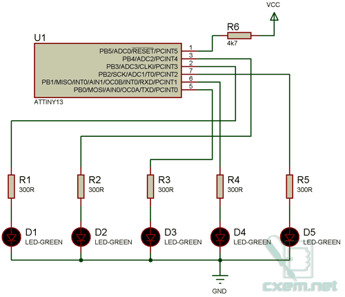
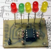
First, start at the end: here’s the final circuit.  It has an ATtiny13, an LED and current-limiting resistor, a few wires, the programmer interface, and that’s about it.  All it does is flash the LED on and off (very much like the classic 555 timer astable multivibrator but with the advantage of no passive components required).  That’s it.  Not much to it.
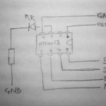
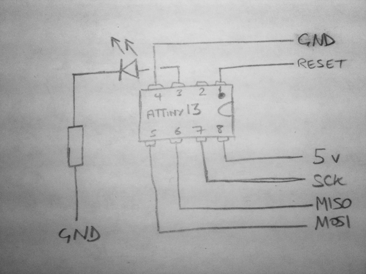
Also, here’s a quick sketch of a circuit diagram too – the inputs all come directly from the ISP interface from the programmer.
Ok, that’s the end result.  Next: how to get there:
  1. Prerequisites (hardware and software)
  2. Build the circuit
  3. Write code
  4. Upload to microprocessor

Prerequisites
You need a programmer (e.g. Pocket Programmer, Adafruit’s USBtinyISP, any number of others, or even use yourarduino),  a way to interface your programmer to your computer (a USB cable would be normal), and a way to interface your programmer to the ATtiny (ISP headers are normal, and here’s a picture of the pinout of the 6-pin header).
Software-wise, there are also myriad choices.  There are different solutions for WindowsMac and Linux.  I’ve only tried a couple of Windows options to date.
Since there are so many options, I’d recommend finding a set of hardware and software that matches your existing equipment and budget that has a decent amount of documentation for troubleshooting.  If you can’t find much out about how to get programmer X working on your computer, try another programmer.
There are more detailed instructions about my tool chain for compiling and programming the chip in the dice post.  I’m using a Pocket Programmer, and WinAVR.
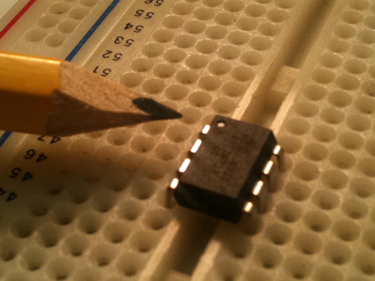
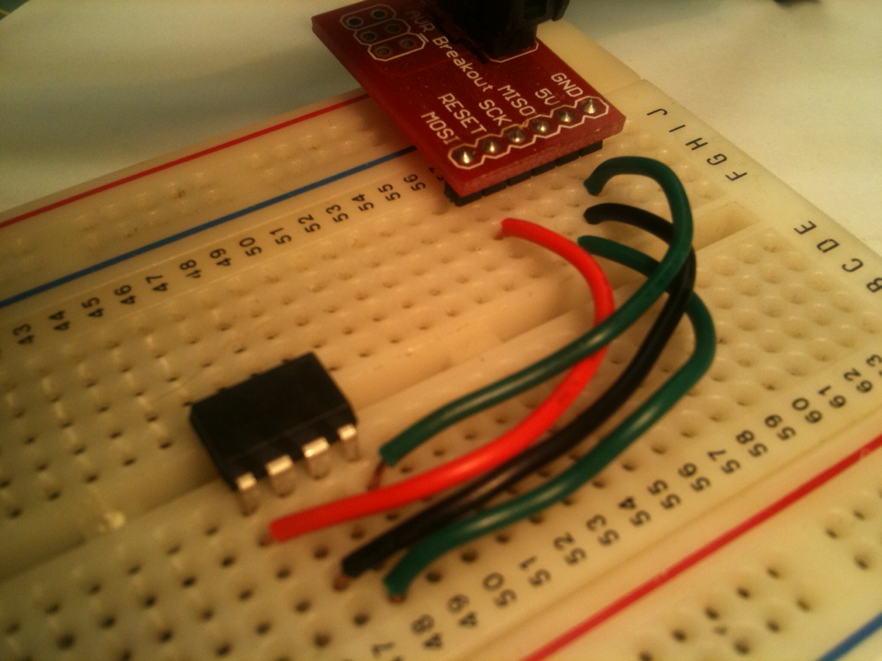
Build Plug the microprocessor into your breadboard.  There’s a notch or a dot at one end of the package to indicate the top, or the position of pin 1 (pointed to in the photo).  Pay attention to which way round the chip is!  The rest of the pins are numbered counter-clockwise from pin 1.
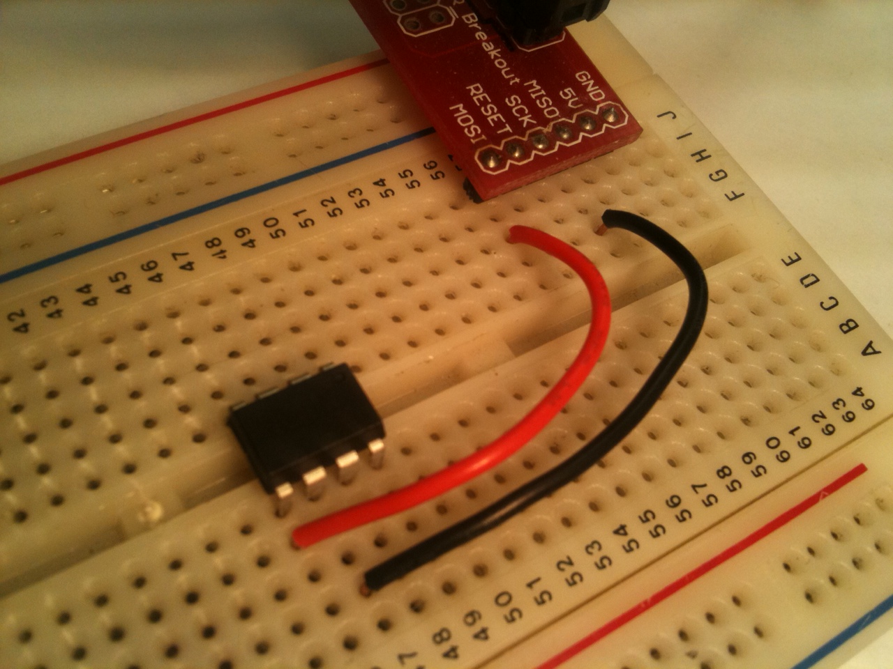
If you have a nice breakout board for your ISP connector, plug it into the breadboard, and start working from that.  Otherwise, refer to the pinout for the ISP and plug wires directly into the socket.
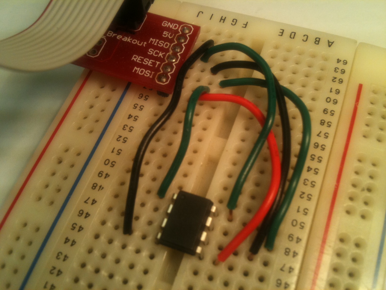
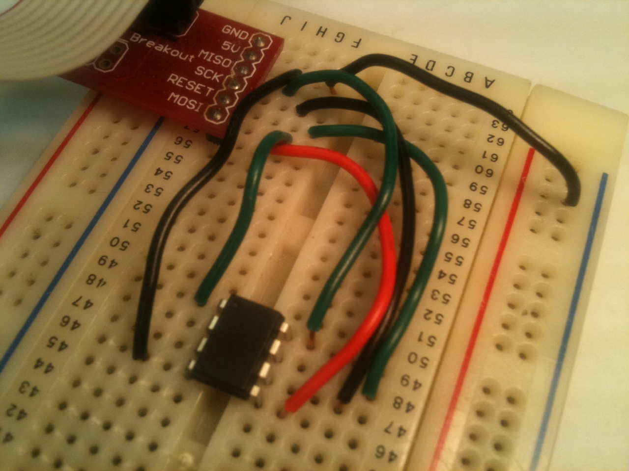
Connect each of the signals from the programmer to your ATtiny – each of MISO, MOSI, SCK, GND, VCC and RESET.  Look at the datasheet for the ATtiny13to see the pinout  (page 2).
(I have a printout of tinkerlog.com’s microcontroller cheat sheet on my desk.  It has pinouts of most common ATtiny and ATmega chips, and ISP headers, and I’m constantly referring to it.)
I want to source current for the LED from the ATtiny, and sink it to ground, so connect a supply line on the edge of the breadboard to GND from the ISP.
Connect the long lead of the LED to pin 3 of the ATtiny.   Connect the short pin to an empty row.  Into that row, connect the resistor (100 or 200 ohms should be fine) and then finally connect the other leg of the resistor to the ground channel.
Write the code
Paste this into your code editor:
/*
 * ATtiny13 LED Flasher
 * File: main.c
 */

#include <stdlib.h>
#include <util/delay.h>

int main(void)
{
    const int msecsDelayPost = 100;

    // Set up Port B pin 4 mode to output
    DDRB = 1<<DDB4;

    // Set up Port B data to be all low
    PORTB = 0;  

    while (1) {
        // Toggle Port B pin 4 output state
        PORTB ^= 1<<PB4;

        // Pause a little while
        _delay_ms (msecsDelayPost);
    }

    return 0;
}
Simple enough.  Save the file as main.c, generate or customize a makefile, and at a command prompt type make all. You should see something like the following:
D:\Projects\AVR>make all

-------- begin --------
avr-gcc (WinAVR 20100110) 4.3.3
Copyright (C) 2008 Free Software Foundation, Inc.
This is free software; see the source for copying conditions.  There is NO
warranty; not even for MERCHANTABILITY or FITNESS FOR A PARTICULAR PURPOSE.

Size before:
AVR Memory Usage
----------------
Device: attiny13

Program:      64 bytes (6.3% Full)
(.text + .data + .bootloader)

Data:          0 bytes (0.0% Full)
(.data + .bss + .noinit)

Compiling C: main.c
avr-gcc -c -mmcu=attiny13 -I. -gdwarf-2 -DF_CPU=1200000UL -Os -funsigned-char -f
unsigned-bitfields -fpack-struct -fshort-enums -Wall -Wstrict-prototypes -Wa,-ad
hlns=./main.lst  -std=gnu99 -MMD -MP -MF .dep/main.o.d main.c -o main.o

Linking: main.elf
avr-gcc -mmcu=attiny13 -I. -gdwarf-2 -DF_CPU=1200000UL -Os -funsigned-char -funs
igned-bitfields -fpack-struct -fshort-enums -Wall -Wstrict-prototypes -Wa,-adhln
s=main.o  -std=gnu99 -MMD -MP -MF .dep/main.elf.d main.o --output main.elf -Wl,-
Map=main.map,--cref     -lm

Creating load file for Flash: main.hex
avr-objcopy -O ihex -R .eeprom -R .fuse -R .lock -R .signature main.elf main.hex

Creating load file for EEPROM: main.eep
avr-objcopy -j .eeprom --set-section-flags=.eeprom="alloc,load" \
        --change-section-lma .eeprom=0 --no-change-warnings -O ihex main.elf mai
n.eep || exit 0

Creating Extended Listing: main.lss
avr-objdump -h -S -z main.elf > main.lss

Creating Symbol Table: main.sym
avr-nm -n main.elf > main.sym

Size after:
AVR Memory Usage
----------------
Device: attiny13

Program:      64 bytes (6.3% Full)
(.text + .data + .bootloader)

Data:          0 bytes (0.0% Full)
(.data + .bss + .noinit)

-------- end --------

D:\Projects\AVR>
Upload to microprocessor
Now the easy bit: plug the programmer into your computer, and type make programat the command prompt.  With any luck, you will see something like
D:\Projects\AVR>make program
avrdude -p attiny13 -P usb     -c usbtiny    -U flash:w:main.hex

avrdude: AVR device initialized and ready to accept instructions

Reading | ################################################## | 100% 0.34s

avrdude: Device signature = 0x1e9007
avrdude: NOTE: FLASH memory has been specified, an erase cycle will be performed

         To disable this feature, specify the -D option.
avrdude: erasing chip
avrdude: reading input file "main.hex"
avrdude: input file main.hex auto detected as Intel Hex
avrdude: writing flash (64 bytes):

Writing | ################################################## | 100% 0.27s

avrdude: 64 bytes of flash written
avrdude: verifying flash memory against main.hex:
avrdude: load data flash data from input file main.hex:
avrdude: input file main.hex auto detected as Intel Hex
avrdude: input file main.hex contains 64 bytes
avrdude: reading on-chip flash data:

Reading | ################################################## | 100% 0.05s

avrdude: verifying ...
avrdude: 64 bytes of flash verified

avrdude: safemode: Fuses OK

avrdude done.  Thank you.

D:\Projects\AVR>
…and the LED should start flashing!


This is the second part of three in attempting to explain how to make the ATtiny13 flash a LED.
Post-Pre-script: If you find this post useful, happen to try out the code, or have any other views or criticisms, please leave a comment. I’d love to hear what you think. – Ian
So last time around, we made a LED flash.  Of course there are other, more elegant ways to do it.  In this post I’ll explore interrupts, and specifically the timer overflow interrupt.  For this I’ll use the same circuit setup from the first article.  If you’re reading this one independently, here’s a circuit diagram:

Interrupts

The structure of programs for these microcontrollers often takes a standard form:
#include <headers>

int main() {
   set_up_routine();

   while (1) {
      do_something_interesting();
   }
   return 1;
}
So once the code’s on the device, after power-up it enters main(), runs whatever setup you want to do, then begins running in an infinite loop doing whatever it is you want the tiny guy to do.
In this model, say you want to get input from devices, you must poll them – that is, every so often your program must go out of its way to figure out whether an input pin has changed from high to low, or some other measurement.  Now this can cause problems.   For example:
#include <headers>

int isSwitchPressed();      // returns 1 if switch is currently pressed down, 0 otherwise

int main() {
   set_up_routine();

   while (1) {
      if (isSwitchPressed()) {
         do_something_that_takes_a_long_time();
      }
   }
   return 1;
}
Let’s say that our interesting thing was to play a fancy little light sequence on a LED. You press the switch, the LED does its thing (or whatever else is in do_something_that_takes_a_long_time), that function returns and again we’re waiting for the switch to be pressed. This is all well and good. If the switch is not pressed, the function returns false, theif’s body is not evaluated, the while loop ends and restarts, and the code tests whether the switch is pressed.
But here’s the rub. Consider:
#include <headers>

int isSwitchPressed();      // returns 1 if switch is currently pressed down, 0 otherwise

int main() {
   set_up_routine();

   while (1) {
      if (isSwitchPressed()) {
         do_something_that_takes_a_long_time();
      } else {
         do_something_else_that_takes_a_long_time();
      }
   }
   return 1;
}
If the switch is not pressed, do_something_else_that_takes_a_long_time() is executed. If you push the switch during the time this function is executing, nothing will happen. The microcontroller will not register that the switch was pressed, and you lose that event happening.
So what if you want a button press during do_something_else_that_takes_a_long_time() to run the regulardo_something_that_takes_a_long_time() code? You could start testing the switch state indo_something_else_that_takes_a_long_time. No, just kidding. That would suck.
This is where interrupts come into play. They do what you might expect them to do – they interrupt the normal code execution. Interrupts can be triggered by different types of events. In the example above you may recognize that a hardware-based interrupt might come to the rescue. Interrupts can also be generated by the microcontroller’s own internal systems, or by your code itself. These are called interrupt vectors. A list of the interrupt vectors for the ATtiny13 is listed in §9.1 in the ATtiny13 datasheet (p. 45).
When an interrupt happens, your way to instruct the µc to do something is through an interrupt handler, aka interrupt service routine, aka ISR. It looks just like a regular function, but you don’t call it directly from your code; it gets executed whenever an interrupt occurs. Once your ISR has completed execution, the program counter jumps back to right where it left of from in your main() loop (or wherever it was when the interrupt was raised) and carries on running.
More pseudocode:
#include <headers>

ISR(interrupt_vector_caused_by_switch_press) {
   do_something_that_takes_a_long_time();
}

int main() {
   set_up_routine();

   while (1) {
      do_something_else_that_takes_a_long_time();
   }
   return 1;
}
So if the button is pressed, and interrupt is raised and our ISR is called. No matter where the program counter is when you press the button, do_something_that_takes_a_long_time() will get called within a few clock cycles. If you haven’t pressed the button then all that gets executed is do_something_else_that_takes_a_long_time().
OK, you get it, enough theory and pseudocode. Moving on…
A word of warning: interrupts give you ways to do all kinds of weird things. Check out this and this for just a hint of the perils that await you!

Implementing Interrupts on ATtiny13 with AVR Libc

_There’s more than one way to skin a cat.  My preferred method is using the AVR Libc code, and the avr-gcc C compiler toolchain, and that’s exclusively what I’ll focus on. _
I’m getting down to brass tacks and jumping around the datasheet a bit here.
The ATtiny13 datasheet §9.1 lists the Timer/Counter Overflow interrupt vector.  Then reading §11.7.1, you learn that in its normal mode, the counter counts upwards, and once it gets to the “top” (there’s only so many bits allocated to store the counter value) it resets back to zero and the TOV0 bit is set. §11.9.6 says that if you enable the Timer/Counter0 Overflow Interrupt by setting the TOIE0 bit to 1 in the TIMSK0 register and interrupts are enabled (“the I-bit in the Status Register is set”), whenever the TOV0 bit is set, the interrupt will be raised.
The timer is what we’re using to generate our interrupts.  It’s an 8-bit register, incremented once per clock tick (unless prescaled – see later).  Since it’s only an 8-bit register its maximum value is 255, therefore once every 256 clock cycles the timer reaches its maximum value and resets back to zero.  If we set up the device properly, when this occurs the Timer/Counter0 Overflow Interrupt will be generated, and we can write a ISR to respond to this interrupt, and flash our timer.
“256 clock cycles?” I hear you ask.  ”That’s not very long.“  We could add a counter variable and toggle the LED once the counter reaches a certain number of overflows.  That might work. The clock runs at around 9.6MHz by default (§6.2.2) and is shipped with the clock freqeuncy divided by 8 (§6.4.2), therefore the 8-bit timer register will overflow ~4688 times per second. Using an 8-bit variable to count those would itself overflow 18 times per second, so we’d need to use a 16-bit variable instead. That gets us into the human timescale, but 65536/4688 gives us a maximum flash time of ~13 seconds. It might work, but there’s a yet more elegant way…
An alternative is to prescale the timer.  This has the effect of using 1 of every n clock ticks to increment the timer counter (§12.1).   You can choose from a number of slowdown factors, all of them are powers of two, and all are listed in the datasheet in §11.9.2, table 11-9.  The slowest rate we can make the timer increment is at 1/1024th the rate of the main system clock (by setting CS02 and CS00 bits to 1 in the TCCR0B register).
If prescaling by x1024, the timer register gets incremented at 1.2MHz/1024, i.e. ~1172 times per second, and thus overflows 4.6 times per second. We could use an 8-bit variable to count the overflows and get a maximum of just under 56 seconds for that one little uint. Sounds better to me.
Here’s a little pseudocode to encapsulate this so far:
ISR(timer_overflow_vector) {
   if (timer_overflow_count > 5) {   // a timer overflow occurs 4.6 times per second
      toggle_led();
      reset_timer_overflow_count();
   }
}

main() {
   initialize_io_port();
   prescale_timer();
   enable_timer_overflow_interrupt();

   while(1) {
      // let ISR handle the LED forever
   }
}
Some of this is gravy, so let’s fill those in with more realistic code:
volatile int timer_overflow_count = 0;

ISR(timer_overflow_vector) {      // TODO
   if (++timer_overflow_count > 5) {   // a timer overflow occurs 4.6 times per second
      // Toggle Port B pin 4 output state
      PORTB ^= 1<<PB4;
      timer_overflow_count = 0;
   }
}

int main(void) {
   // Set up Port B pin 4 mode to output
    DDRB = 1<<DDB4;

   prescale_timer();   // TODO
   enable_timer_overflow_interrupt();   // TODO

   while(1) {
      // let ISR handle the LED forever
   }
}
A little insight from avr-libc helps with the interrupts. By including avr/interrupt.h, the ATtiny13’s Timer/Counter0 Overflow is exposed through the TIM0_OVF_vect interrupt vector. Thus:
#include <avr/interrupt.h>

volatile int timer_overflow_count = 0;

ISR(TIM0_OVF_vect) {
   if (++timer_overflow_count > 5) {   // a timer overflow occurs 4.6 times per second
      // Toggle Port B pin 4 output state
      PORTB ^= 1<<PB4;
      timer_overflow_count = 0;
   }
}

int main(void) {
   // Set up Port B pin 4 mode to output
    DDRB = 1<<DDB4;

   prescale_timer();   // TODO
   enable_timer_overflow_interrupt();   // TODO

   while(1) {
      // let ISR handle the LED forever
   }
}
Prescaling the timer is straightforward and straight from the datasheet: TCCR0B |= (1<<CS02) | (1<<CS00). Setting up the timer overflow interrupt was also defined in the datasheet: TIMSK0 |=1<<TOIE0, and the sei instruction has a helpful sei() macro defined in avr/interrupt.h. Consolidating for our final code:
#include <avr/interrupt.h>

volatile int timer_overflow_count = 0;

ISR(TIM0_OVF_vect) {
   if (++timer_overflow_count > 5) {   // a timer overflow occurs 4.6 times per second
      // Toggle Port B pin 4 output state
      PORTB ^= 1<<PB4;
      timer_overflow_count = 0;
   }
}

int main(void) {
   // Set up Port B pin 4 mode to output
    DDRB = 1<<DDB4;

   // prescale timer to 1/1024th the clock rate
   TCCR0B |= (1<<CS02) | (1<<CS00);

   // enable timer overflow interrupt
   TIMSK0 |=1<<TOIE0;
   sei();

   while(1) {
      // let ISR handle the LED forever
   }
}
References/Acknowledgements: I have to point out the complete awesomeness and of Dean’s Newbie’s Guide to AVR Interrupts on http://www.avrfreaks.net.  It’s awesome.   If you want a great explanation of interrupts, go there and read his tut.


This is the final part of three in attempting to explain how to make the ATtiny13 flash a LED.
In previous posts we’ve looked at creating a simple LED flasher circuit for the ATtiny, a first-pass program for the ATtiny using delays, and a second-pass implementation exploiting timer overflows resulting in a simpler program.  In this article I will explore the power saving modes on the ATtiny13 as an example of how to minimize the power consumption of your circuit.  If your ATTtiny13-, ATtiny80-, or even ATmega-based circuit relies on battery power you will be able to significantly improve the battery life by using the chips’ power saving modes.
In this article we will be using the same circuit developed in the previous posts:

Overview

Looking at the first page of the datasheet you see it lists “Low Power Idle, ADC Noise Reduction, and Power-down Modes”.  Also looking at the modules list in the avr-libc documentation there’s an entry for “<avr/sleep.h>: Power Management and Sleep Modes”.  Starting with example code from the latter, putting the device to sleep doesn’t look very hard:
#include <avr/sleep.h>

    ...
      set_sleep_mode(<mode>);
      sleep_mode();
Then immediately following is this note: “[…] unless your purpose is to completely lock the CPU (until a hardware reset), interrupts need to be enabled before going to sleep.”
So here are my questions: What are the sleep modes and what do they do?  What interrupt vector(s) are available and how do I enable them?
In the datasheet, §7 covers the sleep modes. Right at the top, Table 7-1 summarizes which clocks and oscillators are active, and how the device can be awaken from each of the three supported sleep modes. Looking at §7.1.1-3, the lowest power consumption sleep mode looks like “Power Down Mode” (no surprise), and once in that state it can be awoken by an external interrupt (i.e. a level change on a pin) or through the Watchdog Timer.
Looking at §8.4, the Watchdog timer (WDT) is a separately clocked counter/timer system, capable of generating interrupts which we can use to bring the device out of the Power Down sleep mode. §8.5.2 details the WDT’s register, and in particular Table 8-2 lists how to alter the length of the WDT’s time period.

Implementation

We’ve sen that there’s a way to put the device to sleep, and a way to periodically wake it up.  Last time our LED flasher toggled its LED state each time a timer-based interrupt was generated.  Let’s do the same thing, except put the device to sleep once the LED state has been toggled.  Hopefully this will reduce the power consumption overall, but mainly during the “off” part of the cycle.
Our last implementation using Timer/Counter0 looked like this:
#include <avr/interrupt.h>

volatile int timer_overflow_count = 0;

ISR(TIM0_OVF_vect) {
   if (++timer_overflow_count > 5) {   // a timer overflow occurs 4.6 times per second
      // Toggle Port B pin 4 output state
      PORTB ^= 1<<PB4;
      timer_overflow_count = 0;
   }
}

int main(void) {
   // Set up Port B pin 4 mode to output
    DDRB = 1<<DDB4;

   // prescale timer to 1/1024th the clock rate
   TCCR0B |= (1<<CS02) | (1<<CS00);

   // enable timer overflow interrupt
   TIMSK0 |=1<<TOIE0;
   sei();

   while(1) {
      // let ISR handle the LED forever
   }
}
We need to adjust the timer setup and interrupt we’re using, and add the power mode change. Working on the timer part first, we remove all references to Timer0, and replace them with set up for the WDT. Having read through §8.5.2 it’s clear that operating the WDT is very similar to Timer/Counter0. Setting the WDTIE bit enables WDT interrupts, and combinations of WDP3WDP2WDP1, and WDP0 adjust the prescaling and thus the WDT’s period. Looking at Table 8-2, setting WDP2 and WDP0 gives a 0.5s timer period.
To wrap up replacing the older timer code, we also need to change the interrupt vector we’re using. The documentation for interrupt.h shows that this is called WDT_vect.
Finally, because we can prescale the timer this low, we can also dispense with our old overflow counter.
#include <avr/interrupt.h>

ISR(WDT_vect) {
   // Toggle Port B pin 4 output state
   PORTB ^= 1<<PB4;
}

int main(void) {
   // Set up Port B pin 4 mode to output
    DDRB = 1<<DDB4;

   // prescale timer to 0.5s
   WDTCR |= (1<<WDP2) | (1<<WDP0);

   // Enable watchdog timer interrupts
   WDTCR |= (1<<WDTIE);

   sei(); // Enable global interrupts 

   for (;;) {
      // Waiting for interrupt...
   }
}
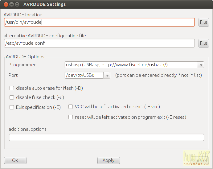
If you set up the circuit and program this into the ATtiny13, the LED should flash on and off with a period of ~1 second, as you would expect. It might be interesting top find out what kind of power savings the sleep modes might give us, so before we add the sleep code let’s measure current drain right now. To make measurements a little easier slow down the flash rate by setting the prescaler to 4 seconds – WDTCR |= (1<<WDP3); – then set your multimeter to measure current and put in the main power loop somewhere. For me the most convenient way was to break the connection between VCC on the ISP breakout and pin 8 on the ATtiny, and insert the ammeter there. I measured 50mA on the mark (whilst the LED was on), and 2.3mA on the space.
To put the device to sleep, the documentation for sleep.h states that
set_sleep_mode(<mode>);
sleep_mode();
is all there is to it. But what parameter do we pass to set_sleep_mode to enable Power Down Mode? Since it’s not in this page of the documentation, if you take a look at the code for the header file itself, at line 253 there’s a #define forSLEEP_MODE_PWR_DOWN that’s applicable to ATtiny13s.
We have already set up the WDT to wake the device from sleep when it raises an interrupt, so as soon as the interrupt handler is complete it is safe to go back to sleep. Working this in, our code now looks like:
#include <avr/interrupt.h>
#include <avr/sleep.h>

ISR(WDT_vect) {
   // Toggle Port B pin 4 output state
   PORTB ^= 1<<PB4;
}

int main(void) {
   // Set up Port B pin 4 mode to output
    DDRB = 1<<DDB4;

   // temporarily prescale timer to 4s so we can measure current
   WDTCR |= (1<<WDP3); // (1<<WDP2) | (1<<WDP0);

   // Enable watchdog timer interrupts
   WDTCR |= (1<<WDTIE);

   sei(); // Enable global interrupts 

   // Use the Power Down sleep mode
   set_sleep_mode(SLEEP_MODE_PWR_DOWN);

   for (;;) {
      sleep_mode();   // go to sleep and wait for interrupt...
   }
}
Plugging in the ammeter again shows 47mA on the mark and 7µA on the space. These readings (and the previous set) are definitely within range of the typical DC characteristics shown in Table 18-1 in the datasheet. If you were using a CR1632 lithium coin cell rated at 125mAh, using the power down mode might increase battery life from 2.4h to 2.6h. Ok, that’s not fantastic but the huge majority of electron juice is used by the LED. If your circuit was a little more complex and had longer periods of inactivity, using the power down saves you a lot of power. If our LED were on for 1/10th of the time it were off, the battery duration change goes from an increase of 8% with the sleep code to an increase of 55%, which seems well worth it to me.